
Direct answer: BESS PCS and EMS integration succeeds or fails on interfaces that are agreed before delivery. Fix the DC voltage window, the communication map and register list, the protection and trip coordination split, and the commissioning sequence in writing. When the battery, the power conversion system and the energy management system each assume a different owner for a signal, the project loses time at the site instead of at the design table.
A battery energy storage system is three control domains working as one: the battery management system protects the cells, the power conversion system moves power to the grid, and the energy management system decides when and how much to dispatch. The boundaries between them are where most integration problems appear.
This guide walks through the interface points that should be defined before equipment ships. It is a technical reference; the final settings and procedures must follow the documentation for the actual equipment.
Assign the DC interface to one owner
The direct-current link between the battery and the power conversion system has no neutral third party. Battery voltage limits, inrush behavior, pre-charge and contactor sequencing all live on this boundary, and each side can assume the other one handles them.
Name one party as the owner of the DC interface and write down the responsibilities. That owner confirms the maximum and minimum voltage, the pre-charge sequence, the contactor control and the protection thresholds across the link. Ambiguity here turns into a site argument at the first energization.
The agreement should also state who provides the DC protection and how a trip is communicated. A protection device that trips without telling the other side can leave the system in an undefined state.
Fix the DC voltage window early
The battery and the power conversion system each have a safe operating voltage range. The overlap is the usable DC voltage window, and it has to be wide enough for the full state of charge range without forcing either side to its limits.
Confirm the window at minimum and maximum state of charge, not only at nominal voltage. A power conversion system selected for the nominal voltage may not accept the battery’s full charge voltage, or may cut off before the battery’s lower limit. State the window as a number with tolerances, and agree which side enforces it.
Also confirm the window under dynamic conditions, because voltage sags during discharge and rises during charge. The protection settings must sit outside the normal operating envelope on both sides, with clear margins.
Define the communication map and registers
The energy management system reads the battery management system and the power conversion system over a communication link, usually Modbus. A register map that is assumed instead of written leads to units, scaling and status flags that do not match.
Freeze the register list, the data types, the scaling and the units before factory testing. Confirm which signals are mandatory for safe operation and which are informational. The same field can be reported in different units by different vendors, so write the units next to every register.
Define the timeouts and loss-of-communication behavior as well. The system should specify what happens when a link drops: whether the power conversion system holds the last setpoint, ramps to a safe state or trips. That behavior must be tested, not assumed.
Agree protection and trip coordination
Protection is shared across the battery management system and the power conversion system, and the split has to be coordinated. The battery protects against overvoltage, undervoltage, overcurrent and temperature. The power conversion system protects against grid faults, islanding and its own overloads.
Write down which device is the primary trip for each condition and which is the backup, along with the expected trip times. If both sides trip at the same threshold, a minor transient can take the system down unnecessarily. If neither trips, a real fault goes unhandled.
Agree how a trip is reported and reset, and whether a trip on one side requires a manual reset on the other. Coordination is easiest to fix on paper and hardest to fix after commissioning has started.
Document the protection settings in a single coordination table that both suppliers sign. The table should list each fault, the primary trip device, the backup device and the expected response time, so that a trip during commissioning can be traced against the agreed setting rather than debated on site.
Plan the commissioning sequence
Commissioning is where the written interfaces are proved. Build the sequence before delivery: insulation and continuity checks, communication link verification, pre-charge and contactor test, protection injection tests, and a controlled first charge and discharge.
Each step should have a pass criterion and an owner, so a failed step is traceable to a party instead of becoming a shared mystery. Reserve time for the interface tests specifically, because they are the steps most likely to reveal a mismatch in the register map or the voltage window.
A controlled first energization with limited power, supervised by all three suppliers, catches integration faults while they are cheap. Rushing straight to full-power dispatch hides the same faults until they appear at the worst time.
| Interface | Owner | Key inputs | Acceptance evidence |
|---|---|---|---|
| DC link | Named owner | Voltage window, pre-charge, contactor sequence | Signed interface agreement |
| Communications | EMS integrator | Register map, units, scaling, timeouts | Frozen register list |
| Protection | BMS and PCS | Trip thresholds, trip times, reset rules | Coordination table |
| Commissioning | Site team | Test sequence, pass criteria, owners | Signed test records |
Complete this table before release to manufacturing. A missing row is a future site stop, and the cheapest time to fill it is before the equipment leaves the factory.
Frequently asked questions
Why does the DC voltage window cause so many integration problems?
The battery and the power conversion system each have a safe voltage range, and the overlap can be narrower than the state of charge range. Fixing the window in writing, with tolerances, removes the most common first-energization surprise.
What should a communication map contain?
It should list the registers, data types, scaling and units for every signal, plus the timeout and loss-of-communication behavior. Units written next to every register prevent silent scaling mistakes.
Who owns protection between the BMS and the PCS?
The split should be written down with a primary and backup trip for each condition, including trip times and reset rules. Both sides tripping at the same threshold can take the system down unnecessarily.
When should the commissioning sequence be agreed?
Before delivery. Each step should have a pass criterion and an owner, so a failed step is traceable and the interface tests get the time they need.
What to send for a technical review
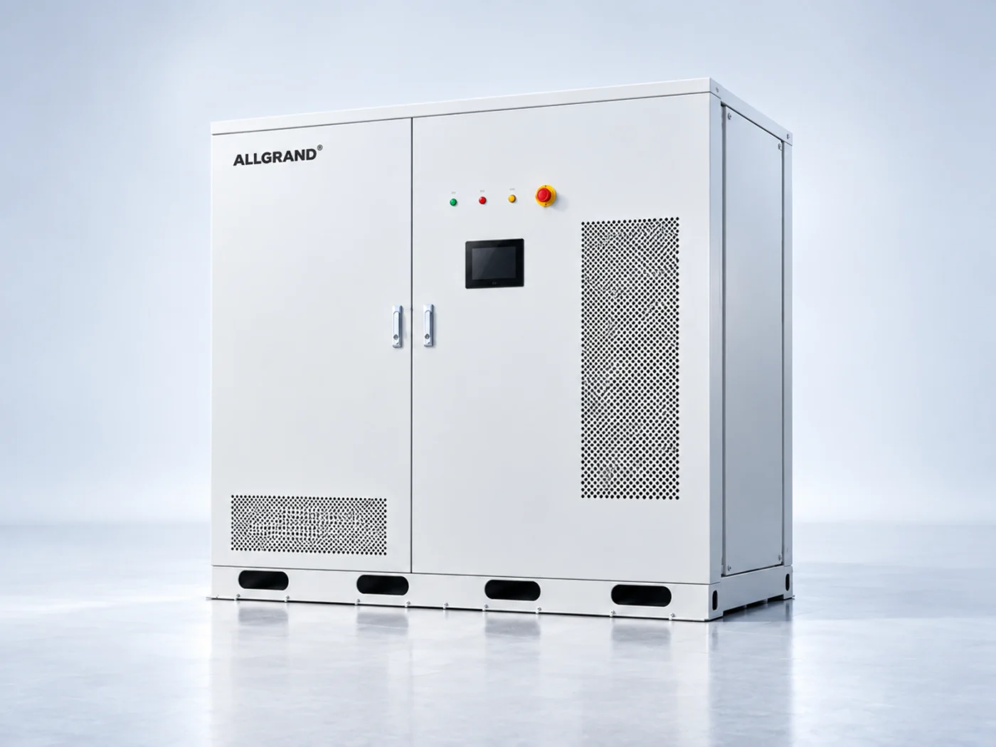
Share the DC voltage window, the register map, the protection settings and the planned commissioning sequence with the AllGrand engineering team. The team can review how the 522 kWh liquid-cooled energy storage cabinet integrates with your power conversion and energy management systems. Read more BESS engineering guides. AllGrand Group has manufactured batteries since 1987 and supplies energy storage systems to customers in more than 100 countries. Integration settings must be confirmed for the actual equipment.
Sources and further reading
- IEC – Energy Storage Standards
- UL Solutions – Energy Storage
- Sandia National Laboratories – Energy Storage
These sources were used to verify general system integration and safety concepts. The interface checklist and commissioning order are original AllGrand editorial work.