
Direct answer: A BESS C-rate is the discharge or charge power divided by the stored energy. Choose the continuous C-rate from the load’s sustained power and duration, not from a short peak, and keep the peak demand inside the system’s time-limited overload rating. Oversizing happens when a brief surge is treated as continuous power, forcing the purchase of energy capacity the site never uses. Match the C-rate to the load profile to buy the right system.
C-rate is one of the least understood numbers in a battery storage specification, partly because it is a ratio rather than a measurement. A one-hour system, a two-hour system and a four-hour system all describe the same concept from different directions: how fast the battery is emptied relative to its size. The mistake is choosing that ratio from the wrong part of the load profile.
This guide explains how to read C-rate and choose it without oversizing. It is a planning reference; the final power, overload and thermal limits must be confirmed by engineering review for the actual site and product.
What C-rate actually measures
C-rate expresses current or power relative to capacity. A 1C discharge would empty the battery’s usable energy in about one hour; a 0.5C discharge would take about two hours; a 0.25C discharge about four hours. It is a shorthand for the power-to-energy ratio, useful for early screening because it lets different systems be compared on one axis.
The shorthand has limits. The actual constraint on the system may come from the cells, the module temperature, the battery management system current limit, the fuses and busbars, the power conversion system or the thermal system. A C-rate that is comfortable for the cells can still exceed what the converter or the cooling loop can sustain.
Continuous and peak C-rate are different
Read the specification for two values: the continuous rating the system can hold, and the time-limited overload it can support for short events such as motor starts. A system described as capable of a high short-duration output may not sustain that output for the full duration of an outage or a demand-charge window.
The load profile usually contains both a sustained level and brief spikes. Size the continuous power and energy from the sustained level, then check that the spikes fall inside the overload rating and its recovery time. If the spikes are frequent, ask for the ramp rate and transient response rather than treating a single C-rate figure as the whole answer.
C-rate, temperature and efficiency interact
Higher discharge rates generate more heat and reduce usable energy because internal resistance converts part of the stored energy into heat. At low temperature the effect is stronger, and at high temperature the thermal system must reject more heat. The result is that the same C-rate can deliver different energy depending on the ambient conditions.
For this reason the C-rate cannot be chosen in isolation. It must be checked against the site’s temperature range and the thermal design. A system that comfortably holds its rated C-rate in a mild climate may derate in a hot or cold one, and the sizing should reflect the worst condition the system must actually serve.
Match C-rate to the load profile
Take the time-stamped load data and separate the sustained demand from the spikes. Divide the sustained power by the required stored energy to find the implied duration, then choose a product whose power and energy sit on either side of that ratio without excessive margin. The goal is a system whose continuous power matches the sustained load and whose energy matches the required duration.
A common error is to take the peak demand and assume the battery must deliver it continuously. That produces a high C-rate requirement and, because energy is then sized to that power, a larger and more expensive system than the duty requires. Handling the peak as an overload instead of a continuous rating removes that inflation.
Where the site runs several distinct services, such as backup and demand-charge control, test the combined duty rather than sizing each service separately. The combined profile can share one battery while the power and energy are set by the most demanding overlapping condition.
| Load signal | Design input | Result |
|---|---|---|
| Sustained demand | Continuous power rating | Sets the power side of the ratio |
| Required duration | Stored energy | Sets the energy side of the ratio |
| Brief spikes | Overload rating and recovery | Keeps the system from oversizing |
| Temperature range | Thermal derating | Confirms the rated C-rate holds |
The table turns the specification into a sequence: power from the sustained load, energy from the duration, overload from the spikes, and a temperature check to confirm the whole combination is valid on site.
Check component limits, not only the cells
After the cells are chosen, trace the complete power path. The battery voltage range must overlap the power conversion system window; the conductors and protection must carry the intended current; and the battery management system, energy management system and converter must agree on control authority. A C-rate that the cells accept is irrelevant if a fuse, busbar or converter limits the system first.
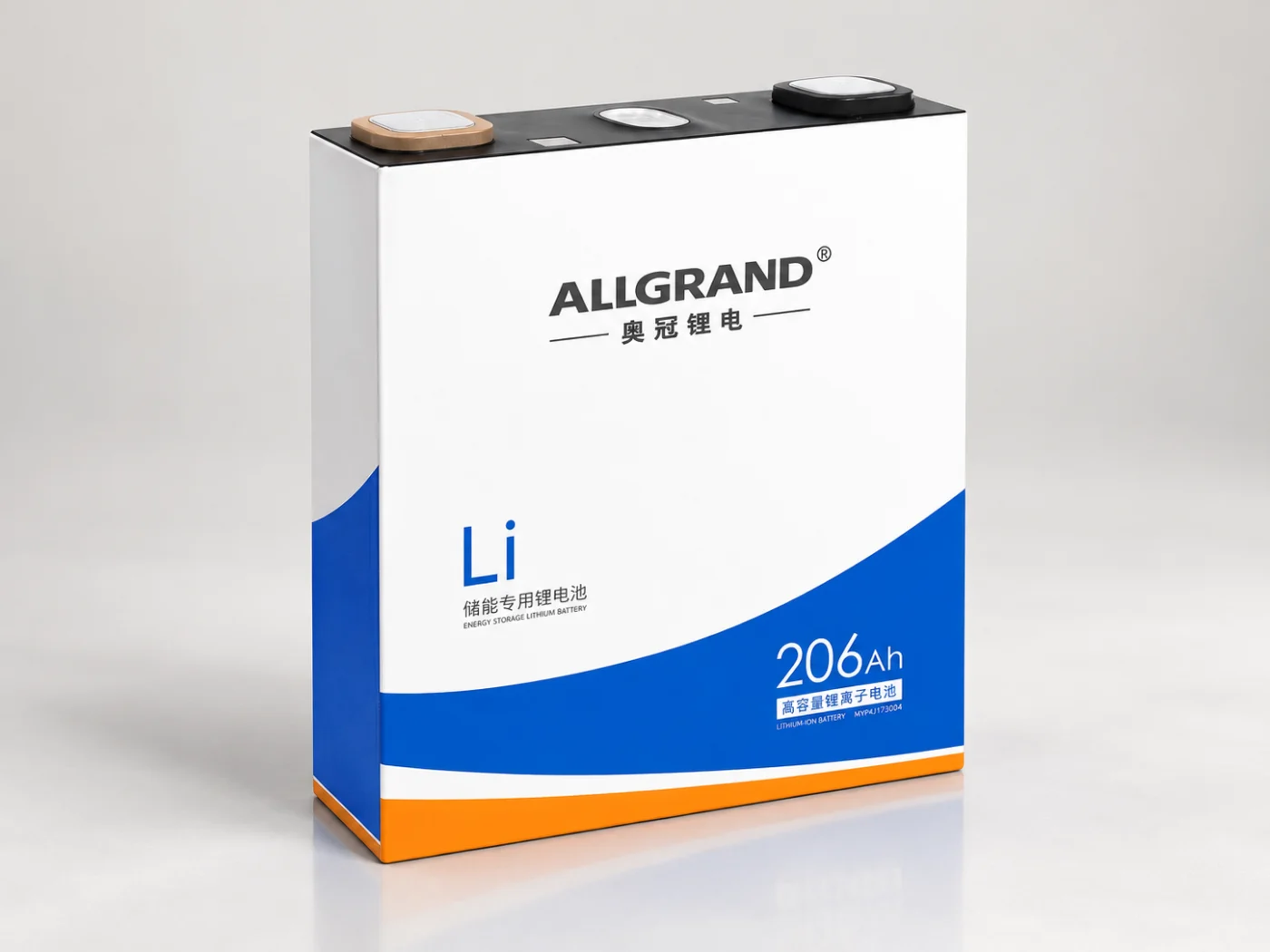
For a reference of the cell and system levels, review the LFP cell energy storage product and the 522 kWh liquid-cooled energy storage cabinet, which pair cells, thermal management and power conversion in one platform. The installed configuration’s continuous and overload ratings must be confirmed by engineering review.
Frequently asked questions
What does 1C mean for a battery storage system?
It means the battery would deliver its usable energy in about one hour, because the power equals the stored energy. A 0.5C system would take about two hours and a 0.25C system about four hours, assuming constant power and no losses.
Should I size from peak or average power?
Size the continuous power from the sustained demand, not the brief peak. Handle short spikes with the system’s time-limited overload rating and its recovery time, so the continuous rating is not inflated by a few seconds of high demand.
Does a higher C-rate reduce delivered energy?
Yes. Higher discharge rates increase internal resistance losses and heat, so less of the stored energy reaches the terminals. Temperature makes the effect stronger, which is why the C-rate must be checked against the site’s ambient range.
What limits the C-rate in practice?
The cells, module temperature, battery management system current limit, fuses, busbars, power conversion system and thermal design can each set the limit. The system’s C-rate is the lowest of these constraints, not the cell rating alone.
What to send for a technical review
Send the site location, fifteen-minute or one-minute load data, required duration, ambient-temperature range and grid configuration to the AllGrand engineering team. The team can review the continuous and overload ratings against the load profile.
Read more energy storage engineering guides from AllGrand. AllGrand Group has manufactured batteries since 1987 and supplies energy storage systems, lead-acid batteries and battery cells to customers in more than 100 countries. Power and overload ratings must be confirmed for the actual site and configuration.
Sources and further reading
- U.S. Department of Energy — Solar Energy and Storage Basics
- NREL — Storage Futures Study
- PNNL — Energy Storage explainer
These sources were used to verify general energy-storage concepts. The C-rate explanation, table and sizing guidance are original AllGrand editorial work.