
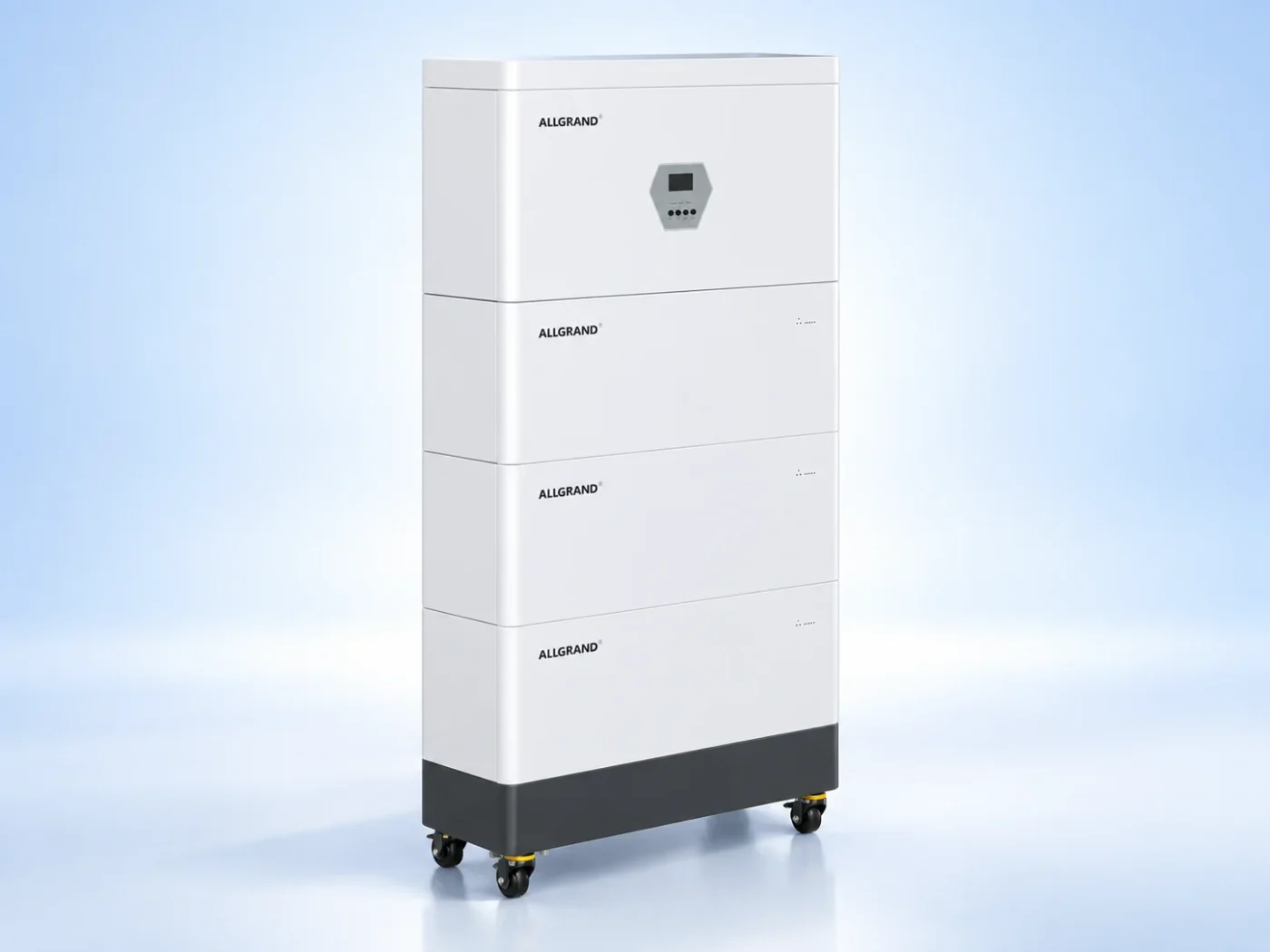
Direct answer: A BESS BMS communication fault means the controller has lost reliable data from one or more battery modules, sensors or slave units. Diagnose the physical layer first: wiring, connectors, termination, addressing, power and grounding. Only after those are confirmed should firmware, configuration or a failed module become the leading explanation, and the system must be isolated before any connector is handled.
A battery management system is a network as much as it is a protection device. The controller exchanges data with module slaves and sensors over a fieldbus such as CAN or RS485. When that link breaks, the controller loses the measurements it needs to protect the battery, so a communication fault usually forces the system into a reduced or stopped state.
This guide gives a diagnostic order that moves from the most common and least invasive checks to the more involved ones. It is a planning reference; the network topology, addresses, voltages and shutdown steps must follow the documentation for the installed system.
Communication faults look like data faults first
The first symptom is often missing or stale data, a list of offline slaves, or a controller alarm that a module is not responding. A single offline module while its neighbors remain online points to that module’s link. A whole bus going offline points to the shared wiring, termination, power or the controller side.
Record which units are affected and whether the fault is intermittent or permanent. Intermittent faults are more likely a loose connector or electrical noise, while a permanent fault suggests a broken wire, a wrong address or a failed transceiver.
Read the fault before touching the network
Start with the alarm text and the system log. Many controllers distinguish between a timeout, a checksum error, a bus-off condition and an address conflict. That distinction tells you where to look before you open an enclosure.
Do not clear the fault and hope it stays away. If the fault is intermittent, clearing it can hide the evidence. Note the time, the operating state and which units were affected so the supplier can read the same history.
Check wiring, termination and addresses first
The physical layer fails far more often than the electronics. Check that each device is connected, that the bus has the required termination resistors at both ends and nowhere else, and that no two devices share the same address. A missing terminator causes reflections, while a duplicated address makes two devices talk over each other.
Inspect connectors for corrosion, moisture or partial insertion. A connector that is not fully seated can work when cold and fail when the cabinet warms, which is why intermittent faults often trace back to a connector rather than a module.
CAN and RS485 checks
For a CAN bus, confirm the high and low lines are not shorted or reversed and that the bus idle voltage is in the expected range. For RS485, confirm the A and B lines are correct and the common reference is present. A reversed pair is a classic commissioning fault that can appear days after installation.
Follow the measurement procedure in the documentation and use the specified tooling. Probing a live battery bus without the right method can damage the transceivers, so the system should be de-energized and isolated first where the procedure requires it.
Bus errors that count up during load and clear at idle often point to electrical noise from the power electronics, so note the operating state when the errors appear.
Power and grounding
Communication faults can be power faults in disguise. A slave that loses its supply drops off the bus, and a floating ground can shift the signal reference far enough to cause errors. Check the slave supply voltage, the ground path and any isolation between the battery potential and the communication side.
Ground loops and electrical noise from the power electronics can also corrupt data. Shielding, where specified, should be continuous and grounded at the defined point. A shield that is grounded at both ends or not at all can create the very noise it was meant to stop.
Firmware and configuration mismatch
After the physical layer is confirmed, look at firmware and configuration. A slave with a different firmware version or a wrong module count can appear as a communication fault even when the wiring is perfect. Compare the installed versions and the bus configuration with the release documentation.
| Step | Check | Typical cause |
|---|---|---|
| 1 | Read the fault and affected units | Local vs whole-bus fault |
| 2 | Verify termination and addressing | Reflections or conflicts |
| 3 | Inspect connectors and wiring | Loose or reversed pair |
| 4 | Check slave power and grounding | Dropped supply or noise |
| 5 | Compare firmware and configuration | Version or setting mismatch |
Working through the list in order finds most faults without replacing hardware. A module swap should come last, after the link itself has been proven healthy.
Restoring the bus and returning to service
After a repair, power the bus back under supervision and confirm every unit is online and exchanging data without errors. Watch the error counters for a while rather than declaring success on the first successful poll. A bus that shows occasional errors is not fixed and will likely fault again.
Record the before and after state, the firmware versions and the configuration. If the fault recurs with the same signature, escalate to the supplier with the log history instead of repeating the same connector check.
Frequently asked questions
Why does my BMS show a module offline?
The module may have lost its communication link, its supply or its unique address. Check the wiring, termination, connector seating and power to that module before suspecting the module electronics themselves.
What is bus termination and why does it matter?
Termination resistors at both ends of the bus prevent signal reflections that corrupt data. A missing terminator or a terminator in the wrong place can cause intermittent communication faults that are hard to reproduce.
Can a firmware mismatch cause a communication fault?
Yes. A slave running a different firmware version or a controller with a wrong module count can reject otherwise valid data and report a communication fault. Compare versions against the release documentation.
Is it safe to probe a live BMS bus?
Only with the specified tooling and procedure. The battery side carries high voltage, and probing incorrectly can damage transceivers. De-energize and isolate the system first where the documentation requires it.
What to send for a technical review
Share the fault text, the affected units, the network topology, firmware versions and the installed system model with the AllGrand engineering team. The team can review the bus evidence and the correct recovery path.
Review the 261 kWh liquid-cooled energy storage cabinet and the lithium energy storage product family, or read more BESS maintenance guides. AllGrand Group has manufactured batteries since 1987 and supplies energy storage systems, lead-acid batteries and cells to customers in more than 100 countries. Diagnostic steps must be confirmed for the actual product and configuration.
Sources and further reading
- IEC — Energy Storage Standards
- UL Solutions — Energy Storage
- Sandia National Laboratories — Energy Storage
These sources were used to verify general battery management and energy-storage safety concepts. The diagnostic order and checklist are original AllGrand editorial work.